Gas analysis in the glass industry & its challenges

The solid, transparent material glass is part of our daily life and can be found in many places and in various forms. No matter whether we hold it in our hands as a water bottle or as a container for medicines or look through a windowpane or car window – glass is everywhere. But how are the different types of glass created? And how can gases be measured and analyzed despite the very high manufacturing temperatures? First, let's take a brief look at the manufacturing process:

How is glass manufactured?

Glass is made from liquid sand and consists mainly of silicon dioxide (SiO2). The most common type of glass in our environment is soda-lime-silica glass. This is made by mixing sand, limestone and soda ash. To produce glass, the raw materials must be mixed and adjusted in the right ratio. Then, the raw materials are melted at very high temperatures.

The melting temperature depends on the type of glass and is usually between 1400 and 1600 °C. The molten glass is then refined, portioned and molded. It is only when cooling down that it transforms into a solidified liquid and features a crystalline structure.

In order for glass to be used for various applications, commercial glass manufacturers alter the properties and appearance of the material. By adding chemicals, they change colors, prevent bubbles in the glass and alter the hardness of the glass, for instance.

Glass products can be divided into the following categories:

  • Packaging standard (bottles, jars)
  • Packaging-specific (pharmaceuticals, perfumes)
  • Float glass (flat glass, e.g. windowpanes, car windows)
  • Fiberglass
  • Optical glass (e.g. lenses, prisms, mirrors)
  • Special technical glass
Portrait of a technician with hard hat in a foundry

Why is gas analysis important in the glass industry?

There are many economic and technical reasons for a continuous gas analysis in the glass industry. The most frequent reasons include:

  • Extending the service life of the furnace
  • Safeguarding high and consistent product quality
  • Reducing energy consumption
  • Ensuring a controlled addition of chemicals
     

Gas analytics provides a significant contribution to optimizing all operational processes and their monitoring, thus helping to achieve the set goals.

M&C gas analysis technology in the glass industry

The installation of gas analysis technology in the glass industry is highly challenging – M&C has already implemented many individualized projects for customers in this industry. The following example is based on an extractive measurement on a melting tank with U-flame gas burner and combustion air pre-heating (regenerators).

Due to the extreme process conditions, it is not uncommon that temperatures of +1500 °C and a high dust level prevail there. But also at the installation site outside the process, very high temperatures prevail and the radiant heat from the melting operation is enormous.

In this process, two burners and two regenerators are operated alternately due to the very high temperatures. The sample gas is extracted in turns at the measuring points MP1 and MP2 (see diagram) and fed to a gas analyzer to determine the concentration. Carbon monoxide, nitrogen oxides and oxygen are measured. Both measuring points were tightly defined in advance at all plants in order to achieve a high degree of comparability.

The M&C approach

For gas sampling and sample gas filtering, a water-cooled and pneumatically movable sampling system is installed in both torch necks (MP1/MP2).

The system, in which an SP180-H probe is installed, offers special functions due to the difficult conditions.

Traversing device for the sampling system

To avoid destruction in the event of a supply failure, the sampling system has an “emergency retraction device”. The system can be moved pneumatically, and the activation is synchronized with the burner control of the glass melting tank.
The sampling system is automatically withdrawn from the process as soon as one of the following limits is exceeded:

  • Compressed air < 4 bar
  • Water flow rate < 14 Nl/min
  • Cooling water temperature > 60 °C
     

To shield off the radiant heat when the probe is pulled out, an automatically closing quick-release cap is used.

Cooling the application

To protect the metallic sample tube from thermal destruction and to prevent catalytic oxidation of the gas components to be measured, additional cooling of the sample tube is indispensable.

The cooling results from two annular gaps in a double-jacket tube with a water inlet and return flow. Cold water is supplied through the water inlet and cools the sample tube to prevent melting in the process. When passing through, the water heats up at the tip of the sample tube due to the high temperatures in the process. However, it must not exceed 60 °C – otherwise the probe is automatically pulled out for protection. Also, if the pressure of the compressed air supply is too low and the water flow rate is insufficient, this will trigger the retraction.

The procedure in the gas analysis system
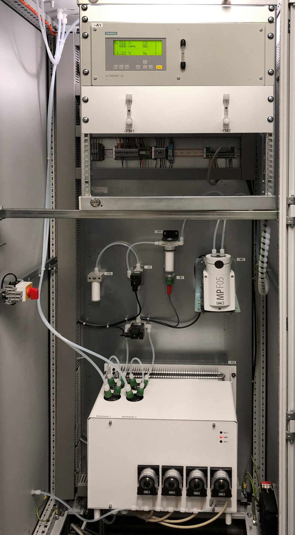
Frontal view of an opened system cabinet

The gas extracted from the measuring points is directed to the gas analysis cabinet via two sample gas lines.

Both sample gas paths are first passed through the Compressor Gas Cooler ECS-4G  to dry the sample gas.

The measuring point switchover (MP1/MP2) is performed by a 3/2-Way Solenoid Valve installed in the system.

In addition, the built-in Humidity Sensor LA/LA1.4 is responsible for monitoring the function of the cooler.

In this case, the subsequent filtering of the sample gas is performed by the Universal Filter FP-2T.

For a continuous and reliable sample gas extraction, we integrate the Bellows Pump MP-F05 into the system.

In addition, the Flow Meters FM40 and FM150 ensure continuous flow monitoring by controlling the sample gas flow to the analyzer and the bypass. Through another solenoid valve, ambient air is drawn in via the Ambient Air Suction Filter SP52. The filtered air can then be used as zero gas and provided to the analyzer for its daily adjustment.

Since measurements are carried out alternately at only one measuring point at a time, the system requires only one gas analyzer for measuring CO, NO and O2.

Our conclusion:

For several years, this solution has now been in continuous operation at our customer’s plant and has proved to be successful in technical and economic terms. Despite the special requirements, the gas analysis works perfectly due to the customized product solution.

You also have special requirements and need an individual system for gas analysis? Or do you have specific issues for which we can provide assistance? Our experts will be glad to advise you and find the right solution for you. Your first contact persons are:

Further Topics of Interest